Excellence ortho
Universal skeletal anchoring system

A-1
BEYOND THE LIMITS
LOWER INFRA-ZYGOMATIC AREA
The most common technique to place a mini-screw in this area involves beginning with a 90° insertion angle, 1 mm above the mucogingival junction, then to progressively decrease the insertion angle down to approximately 60-70° as the screw is inserted.


2 x 12 mm
2 x 10 mm
2 x 8 mm
ZONES OF THE MANDIBLE
The most common areas to place a mini-screw in the mandible are the alveolar process, the mandibular symphysis, the retromolar triangle, the retromolar fossa and the buccal plate on the external oblique line.

EXTERNAL OBLIQUE LINE AREA
This area is located at the front of the external oblique line.

2 x 10 mm

RETROMOLAR TRIANGLE
The retromolar triangle is a good location for a mini-screw, in particular to correct mesially tilted molars.


RETROMOLAR FOSSA AREA (PV BS)
The retromolar fossa area (PVBS) is located at the outer edge of the retromolar triangle.

2 x 17 mm IZC

MEDIAN PALATINE LINE
The most common location to place a mini-screw in the palate is behind the incisive foramen, 2 or 3 mm away from the median suture of the palate. Avoid somewhat larger palatine foramen when placing interdental mini-screws in the palate.

2 x 10 mm

PLACEMENT OF MINI-SCREWS IN INTERRADICULAR SITES
Cortical bone 0.50 x 2 = 1 mm
PDL 0.25 x 2 = 0.50
The minimum required space is 3 mm
This criterion applies to vestibular and palatine interdental mini-screws.


UNIVERSAL INSERTION PROCEDURE
This quick overview of the procedure does not include all the scientific details. For full information, you must attend a training course on mini-screws.
1
Diagnostic tools and treatment planning.

2
Disinfect and anaesthetize
the mucosa (topical or inject a few drops)

3
Assess the thickness of the mucosa in order to select screw length.

4
Select the length and diameter of the screw

5
Prepare the bone by making a notch in the selected area. Some zones need to be drilled ahead of time to place the screw.

6
When you place the mini-screw, control insertion torque to avoid fracturing or bending the screw.

7
Check primary stability, then load the mini-screw with 30% of the appropriate level of force.

INSERTION PROCEDURE FOR THE UPPER INFRA-ZYGOMATIC
1 – Identify the zone and make a notch in the bone with a sharp or cutting instrument.
2 – Insert the mini-screw directly into the upper IZC.


3 – The insertion route is from back to front in order to protect retromaxillary tissues.
INSERTION PROCEDURE FOR THE INFRA-ZYGOMATIC ZONE
STEP 1: Insert the mini-screw 1 mm above the gingival mucosa.
90° junction

STEP 2: Continue the insertion while turning the screw until it reaches 60 to 70°

STEP 3: Apply 30% of the indicated force to complete the mini-screw

DESING MINI-SCREW
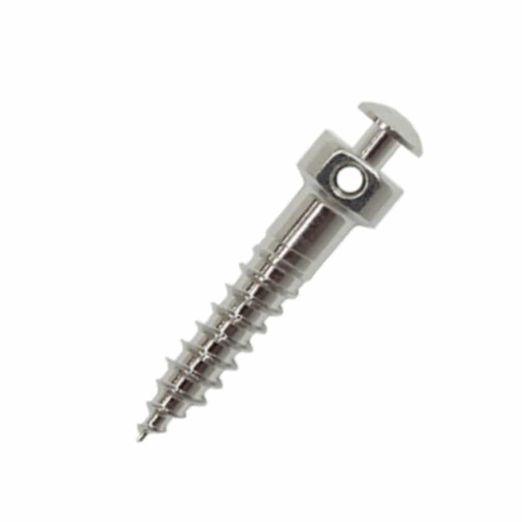
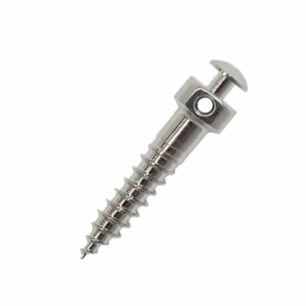
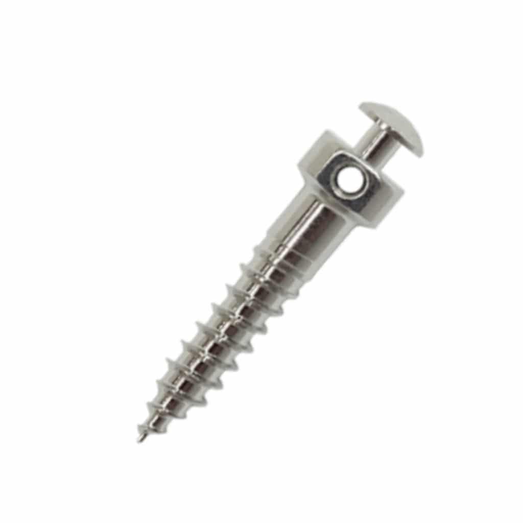
The A-1 left dynamometric screw has a rectangular 2-mm hole for threads up to 0.019 x 0.025.

INSERTION PROCEDURE FOR PV BS
STEP 1: Identify the zone and make a notch in the bone with an instrument.

STEP 2: Limit the zone with your thumb

Position yourself in front of the patient to place the mini-screw in the retromolar zone (PV BS)


2 X 17 IZC
RIGHT BUCCAL PLATE (EXTERNAL OBLIQUE LINE)
INSERTION PROCEDURE
To place the mini-screw on the right side, always stand or sit at a 12 o’clock position behind the patient.

STEP 1: The patient must slide their mandible on the side where the mini-screw will be placed.

STEP 2: Identify the buccal plate, “feel the bone”, and make a notch in the bone with an instrument.

STEP 3: Depending on bone density, you may need to drill a pilot hole. Use your thumb to limit and protect surrounding tissues while inserting the mini-screw.

LEFT BUCCAL PLATE (EXTERNAL OBLIQUE LINE)
INSERTION PROCEDURE
Always stand or sit at the 2 o’clock position behind the patient to place a mini-screw in the left side.

STEP 1: The patient must slide their mandible towards the opposite side of where the mini-screw will be placed.

STEP 2: Identify the buccal plate,
“feel the bone”, and make a notch in the bone with the instrument.

STEP 3: Depending on bone density, you may need to drill a pilot hole. Insert the mini-screw with your thumb to limit and protect surrounding tissues.

A-1
BEYOND THE LIMITS

DESING MINI-SCREW
A-1 mini-screws are in surgical stainless steel (UNS S31673) and manufactured to be solid enough to withstand insertion forces regardless of the level of torque applied to the higher-density maxillary and mandibular bones. While the A-1 mini-screws have self-drilling tips, it may still be necessary to drill a pilot hole in very hard and dense bone.

MINI-SCREW STABILITY
Original tissues

Primary stability 30% of indicated force

Limited stability does not apply additional force

Secondary stability indicated force at 100

BIOLOGICAL ACTIVATION SYSTEM
The biological activation system is a protocol designed to activate the bone’s natural response by creating shallow holes in the cortical bone, then removing the mini-screw.
- Amplifies inflammatory response and natural biological activity.
- Decreases bone density activation.
- These two events stimulate bone remodeling and facilitate tooth movement.


2.0 x 7 mm
ANATOMY FOR MINI-SCREWS
There are two major groups of anatomical structures where mini-screws can be placed.
1 INTERRADICULAR
The mini-screw is placed between the roots of teeth.

- Labial side between the maxillary and mandibular roots.
- A hard palate between the roots.
2 EXTRARADICULAR
The mini-screw is placed outside the roots

- Zygomatic arch
- Upper and lower infra-zygomatic areas.
- External oblique line or mandibular plate.
- Retromolar fossa and triangle.
- Median palatine line (hard palate).
- Mandibular symphysis.
MAXILLA
In addition to the hard palate, the maxilla has three areas that are suitable for skeletal anchoring: the zygomatic process, the infra-zygomatic crest and the alveolar process.

INFRA-ZYGOMATIC CREST
When placing the mini-screws, the infra-zygomatic crest is divided into upper and lower areas depending on the patient’s bone thickness and density.

UPPER INFRA-ZYGOMATIC AREA
The technique used to place a mini-screw in the upper infra-zygomatic crest area is direct insertion. The screw’s long gingival collar is important to protect the patient’s mucosa in this area during functional movements.


2 x 17 mm IZC


